H.264 compression explained in detail with coding examples
H.264 compression explained in detail with coding examples


Video coding and decoding is a process of compressing and decompressing a digital video signal.
This is me exploring the concepts of H264 video compression based on Ian E. Richardson - H264 book and other online resources. The goal is to implement as much as I know how to these concepts in Python. It's an ongoing article and I add to it when I have the time.
Capture
A natural visual scene is spatially and temporally continuous. In simpler terms; spatially means capturing frames in a 2-D square, temporally capturing 2-D squares in regular intervals in time.
Progressive and Interlaced sampling
A video signal capture might be using progressive sampling (series of complete frames) or interlaced sampling (series of horizontal odd or even frames capturing half of the frame information).
Color spaces
The way of capturing color information.
RGB
Red, Green and Blue can create any color in varying proportions.
YCrCb
Separating luminance from the color. Human Visual System (HVS) is less sensitive to color than luminance. It's a more efficient way of representing a frame for the human eye.
This color model uses Y to represent the brightness and two color channels Cb (chroma blue) and Cr (chroma red). The YCbCr can be derived from RGB and it also can be converted back to RGB. We can produce all the colors without using the green.
Y = 0.299R + 0.587G + 0.114BOnce we had the luma, we can split the colors (chroma blue and red):
b = 0.564(B - Y)
Cr = 0.713(R - Y)
And we can also convert it back and even get the green by using YCbCr.
R = Y + 1.402Cr
B = Y + 1.772Cb
G = Y - 0.344Cb - 0.714Cr
We can use the coefficients from the standard BT.601 that was recommended by the group ITU-R* .
The complete description of a color image is given by Y, the luminance component and three color differences, Cr, Cb and Cg that represent the difference between the color intensity and the mean luminance.
So far this representation has little obvious merit since we now have four components instead of three in RGB. However, Cr,Cg,Cb is a constant and so only two of the three chorminance components need to be stored or transmitted since the third component can always calculated from the other two. So only the luma (Y) and red and blue Cr,Cb are transmitted.
Y:Cr:Cb has an important advantage over RGB in that the Cr and Cb components may be represented with lower resolution than Y because the HVS is less sensitive to color than luminance. This reduces the amount of data required to represent the chrominance components without having a too obvious effect on visual quality. Representing chroma with a lower resolution than luma is simple but effective form of image compression.
YCrCb sampling formats
Chroma subsampling compression levels are referred to as ratios, such as 4:4:4, 4:2:2 and 4:2:0. A 4:4:4 ratio is actually uncompressed, as the amount of chroma data is equal to the amount of brightness data. In a 4:2:2 ratio, half of the colour data is present compared to a 4:4:4 ratio. In a 4:2:0 ratio, a quarter of the color data is present compared to a 4:4:4 ratio.
These schemas are known as subsampling systems and are expressed as a 3 part ratio - a:x:y which defines the chroma resolution in relation to a a x 2 block of luma pixels.
ais the horizontal sampling reference (usually 4)xis the number of chroma samples in the first row ofapixels (horizontal resolution in relation toa)yis the number of changes of chroma samples between the first and seconds rows ofapixels.
An exception to this exists with 4:1:0, which provides a single chroma sample within each 4 x 4 block of luma resolution.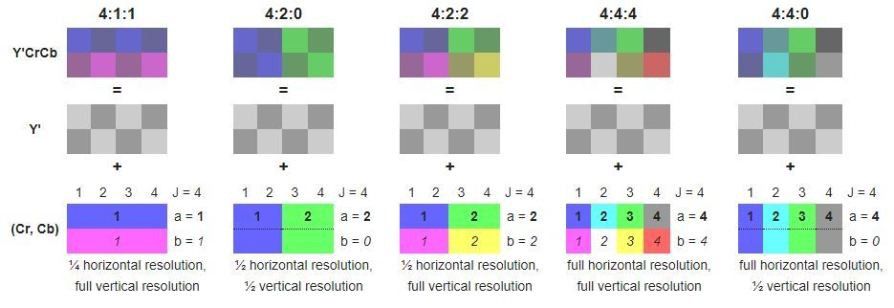
Another visual explanation of chroma subsampling:
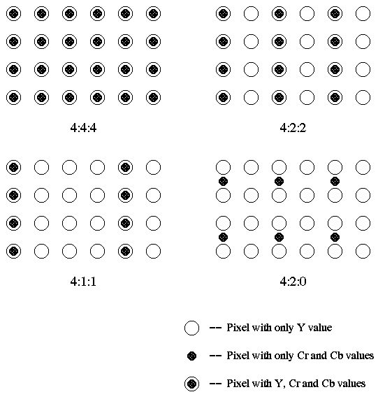
4:2:0 is widely used sampling format (YUV, YVI12) where Cr and Cb have each half the horizontal and vertical resolution of Y. 4:2:0 is widely used in video conferencing, digital television and DVD storage.
From the example above we see thay 4:2:0 chroma subsampling requires half as many bits as 4:4:4 (non compressed) format.
Let's reason about the number of bits required to represent an image:
Image resolution: 720x576 px

Y resolution: 720x576 px, each pixel represented with 8 bits (0-255 decimal)

4:4:4 Cr, Cb, Y; total number of bits: 720x576x8x3 = 9953280 bits

4:2:0 Cr, Cb, Y; total number of bits: 720x572x8 + 360x288x8x2 = 4976640 bits
4:2:0 sampling is sometimes described as 12 bits per pixel.
Video Formats
The video compression algorithms can compress a wide variety of video frame formats. In practice, it is common to capture or convert to one of a set of ‘intermediate formats’ prior to compression and transmission.
The Common Intermediate Format (CIF) is the basis for a popular set of formats:
| Format | Video Resolution |
|---|---|
| SQCIF | 128 × 96 |
| QCIF | 176 × 144 |
| SIF(525) | 352 x 240 |
| CIF/SIF(625) | 352 × 288 |
| 4SIF(525) | 704 x 480 |
| 4CIF/4SIF(625) | 704 × 576 |
| 16CIF | 1408 × 1152 |
Quality
In order to specify, evaluate and compare video communication systems it is necessary to
determine the quality of the video images displayed to the viewer. Our perception of a visual scene is formed by a complex interaction between the components
of the Human Visual System (HVS), the eye and the brain. This is called a subjective quality measurement.
Peak Signal to Noise Ratio (PSNR) is measured on a logarithmic scale and depends on
the mean squared error (MSE) between an original and an impaired image or video frame,
relative to (2n − 1)2, the square of the highest-possible signal value in the image, where n is the number of bits per image sample.
PSNR can be calculated easily and quickly and is therefore a very popular quality measure,
widely used to compare the ‘quality’ of compressed and decompressed video images.
Video Coding Concepts
A video CODEC encodes a source image or video sequence into a compressed
form and decodes this to produce a copy or approximation of the source sequence. If the decoded video sequence is identical to the original, then the coding process is lossless; if the decoded sequence differs from the original, the process is lossy.
A video encoder consists of three main functional units: a prediction model,a
spatial model and an entropy encoder.
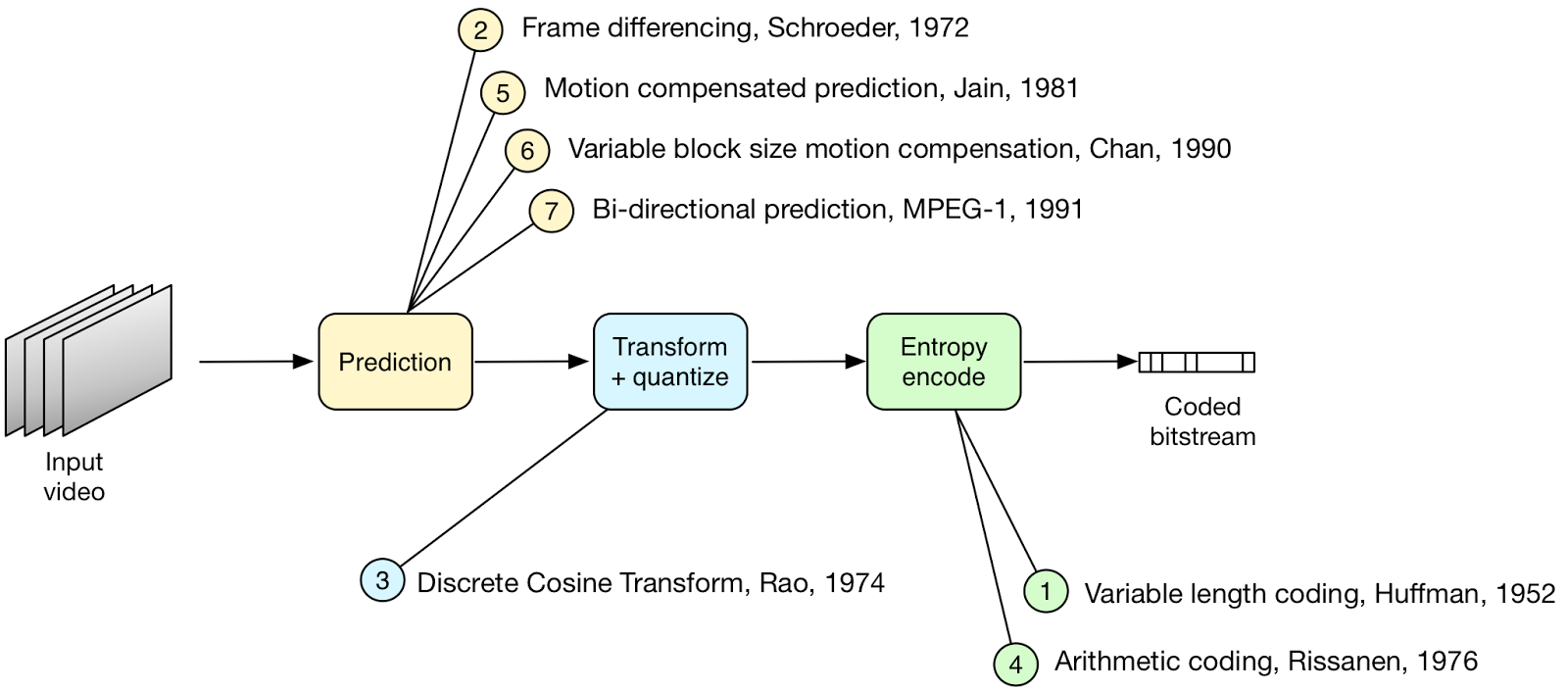
The input to the prediction model is an uncompressed video sequence. The prediction model attempts to reduce redundancy by exploiting the similarities between neighboring video frames and/or neighboring image samples, typically by constructing a prediction of the current video frame or block of video data.
The parameters of the prediction model, i.e. intra-prediction mode(s) or inter prediction
mode(s) and motion vectors, and the spatial model, i.e. coefficients, are compressed by the entropy encoder. This removes statistical redundancy in the data, for example representing commonly occurring vectors and coefficients by short binary codes.
Prediction
- Spatial prediction (from previously coded image samples in the same frame)
- Temporal prediction (from previously coded image samples)
Motion compensated prediction of a macro-block
The macro-block, corresponding to a 16 × 16-pixel region of a frame, is the basic unit for
motion compensated prediction in a number of important visual coding standards including
MPEG-1, MPEG-2, MPEG-4 Visual, H.261, H.263 and H.264.
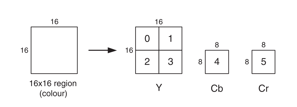
16 × 16-pixel region of the source frame is represented by 256 luminance samples arranged in four 8 × 8-sample blocks, 64 red chrominance samples in one 8 × 8 block and 64 blue chrominance samples in one 8 × 8 block, giving a total of six 8 × 8 blocks.
Motion estimation
Motion estimation of a macroblock involves finding a 16 × 16-sample region in a reference
frame that closely matches the current macroblock. The reference frame is a previously
encoded frame from the sequence and may be before or after the current frame in display
order.
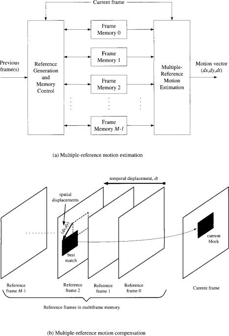


Instead of 16 × 16 a 4 × 4 block might give the smallest residual energy. However,
a smaller block size leads to increased complexity, with more search operations to be carried out, and an increase in the number of motion vectors that need to be transmitted.
An effective compromise is to adapt the block size to the picture characteristics, for example choosing a large block size in flat, homogeneous regions of a frame and choosing a small block size around areas of high detail and complex motion.
The performance gain tends to diminish as the interpolation steps increase. A motion-compensated reference frame, the previous frame in the sequence, is subtracted
from the current frame and the energy of the residual, approximated by the Sum of Absolute Errors (SAE). A lower SAE indicates better motion compensation
performance.
H.264 Syntax Overview
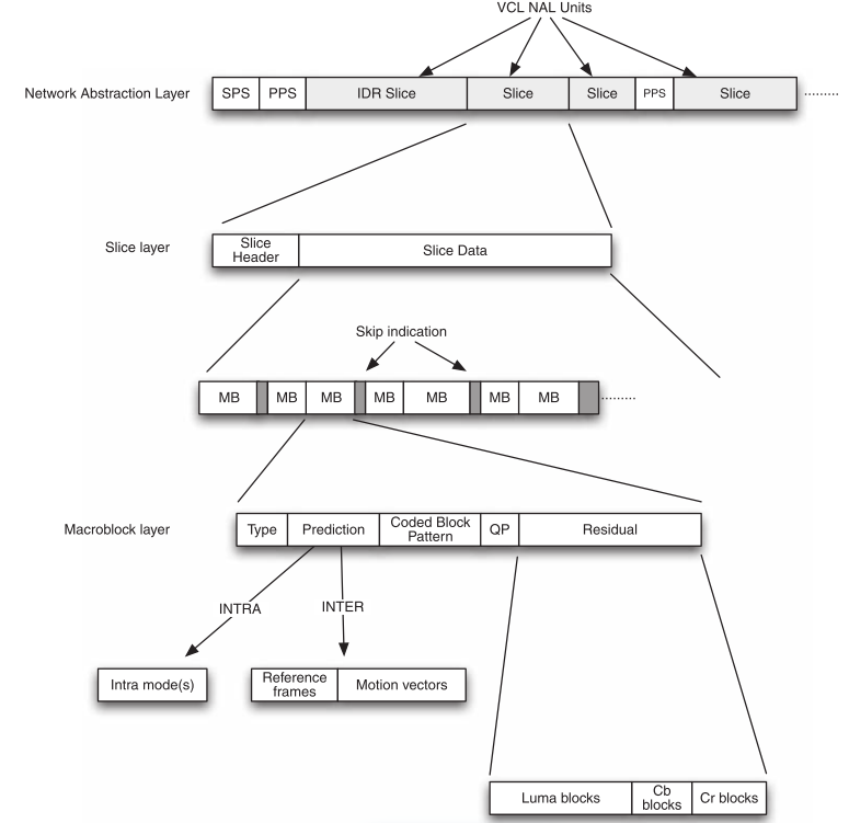
Network Abstraction Layer (NAL) consists of a series of NALUnits (NALU).
Sequence Parameter Sets (SPS) and Picture Parameter Sets (PPS) are NAL units that signal certain common control parameters to the decoder.
At the slice layer, each slice consists of a Slice Header and Slice Data.
The Slice Data is a series of coded macroblocks (MB) and skip macroblock indicators which signal that certain macroblock positions contain no data.
MB type : I/intra coded, P/inter coded from one reference frame, B/inter coded from one or two reference frames.
- Prediction information : prediction mode(s) for an I macroblock, choice of reference frame(s) and motion vectors for a P or B macroblock.
- Coded Block Pattern CBP : indicates which luma and chroma blocks contain non-zero residual coefficients.
- Quantization Parameter QP, for macroblocks with CBP = 0.
- Residual data, for blocks containing non-zero residual coefficients.
H.264 Prediction
For every macroblock, a prediction is created, an attempt to duplicate the information contained in the macro-block using previously coded data, and subtracted from the macro-block to form a residual.An accurate prediction means that the residual contains very
little data and this in turn leads to good compression performance.
Macroblock prediction
Types of Macroblocks:
- I These are completely refreshed, new data. They only reference itself and do not rely on any other image in order for it to be decoded correctly. The first image in a GOP must be of this type. Also known as Intra-prediction
- P (Predicted) – These use one or more previously decoded reference images in order to construct a full picture.
- B (Bi-Directional Predicted) – These use previously decoded reference images and future displayed images to be constructed. As a result, the order that the images are encoded and decoded will be different to that displayed.
H.264/AVC supports a wide range of prediction options – intra prediction using data within the current frame, inter prediction using motion compensated prediction from previously coded frames. Additionally H.264 tries to select the optimal combination of parameters for each macroblock; prediction block size, specialized prediction modes (Direct, Weighted) and other filters to reduce number of bits.
Intra prediction
An intra (I) macroblock is coded without referring to any data outside the current slice. For a typical block of luma or chroma samples, there is a relatively high correlation between samples in the block and samples that are immediately adjacent to the block. Intra prediction therefore uses samples from adjacent, previously coded blocks to predict the values in the current block.